

4. RESISTANCE -RESISTORS AND RESISTOR CIRCUITS - Resistance is the opposition to current flow in various degrees. The practical unit of resistance is called the ohm. A resistor on one ohm is physically very large but provides only a small resistance to current flow. A resistor of one million ohm's is physically small but presents a high resistance to current flow. A resistance that develops 0.24 calorie of heat when one ampere of current flows through it for one second has one ohm of resistance. The unit of resistance is often represented by the Greek letter omega. Resistors are often made of thin layers of carbon or lengths of small copper wire. They can also be thin deposited layers of metallic material. An image of a few resistor types is shown below.What is electrical current? Electrical current, represented by the letter "I" in formulas, and it is the flow or rate of electric charge. This flowing electric charge is typically carried by moving electrons in a metallic conductor or electronic components such as resistors or transistors as an example. The unit of electrical current is the ampere, named after a french mathematician, Andre Marie Ampere. What is electrical voltage? Electrical voltage is represented by the letter "V" in formulas and it is the electrical pressure a moving charge is under. In the case of a static charge, one that is not moving, then voltage is the potential difference or pressure of the charge. The relationship between current (I), resistance (R), and voltage (V) is represented by the formulas developed in Ohm's law. We will study that in section 5 below.RESISTORS AND RESISTOR CIRCUITS-Resistors can be connected in series (end to end), or in parallel (across one another), or in a combination of series and parallel. If you connect two, 1/4 watt, 100 ohm resistors across one another (i.e. in parallel) then the total resistance in ohms is one half of one of the resistors. In this example the resistance would be 50 ohms. The wattage doubles as the current is now split between the two resistors. The combination can now handle up to one half a watt safely. If the two resistors were connected end-to-end (i.e. in series) the resistances add and in this case would be 200 ohms. The wattage in this series case stays the same, 1/4 watt. This information is handy to know as it is easy to calculate in your head and will allow you to devise additional resister values from a limited resistor bench stock.
RESISTORS IN SERIES: Connecting resistors in a string one pigtail to another is called connecting them in series. When connected this way the resistance of one resistor adds to the next in line. For example a 100 ohm resistor in series with a 500 ohm resistor is the same as having a 600 ohm resistor. The wattage capability stays the same, in other words if the resistors are all 1/4 watt the string is 1/4 watt.Resistance in series resistance simply adds: R = R1 + R2. This can be extended for more resistors: R = R1 + R2 + R3 + R4 + ...RESISTORS IN PARALLEL: When resistors are connected in parallel (parallel; meaning they are tied across one another) their combined resistance is less than any of the individual resistances. There is a special equation for the combined resistance of two resistors R1 and R2:
Combined
resistance of
two resistors in parallel: |
R
=
|
R1
× R2
|
R1
+ R2
|
For more than two resistors connected in parallel a more difficult equation must be used. This adds up the reciprocal ("one over") of each resistance to give the reciprocal of the combined resistance, R:
1
|
=
|
1
|
+
|
1
|
+
|
1
|
R
|
R1
|
R2
|
R3
|
The simpler equation for two resistors in parallel is much easier to use!Note that the combined resistance in parallel will always be less than any of the individual resistances.Resistor values are measured in ohms. A thousand ohms is written as 1k to eliminate all the zeros. The k represents three zeros. A million ohms is represented by 1M. Therefore; 1000 ohms = 1k ohm and 1000k ohms = 1M ohm. Since resistors are so small their value is marked by a color code.RESISTOR COLOR CODES - Resistors use color coded stripes to indicate their value in ohms. 0=Black, 1=Brown, 2=Red, 3=Orange, 4=Yellow, 5=Green, 6=Blue, 7=Purple, 8=Gray, 9=White.
| Black | Brown | Red | Orange | Yellow |
| 0 | 1 | 2 | 3 | 4 |
| Green | Blue | Violet | Grey | White | |
| 5 | 6 | 7 | 8 | 9 |
5. OHMS
LAW
Ohm's
Law is extremely important in learning basic electronics.
What
is Ohm's Law? Ohm's Law is a formula that describes the relationship
between resistance, current and voltage in an electrical circuit. The
formula is R (resistance in ohms) = (equals) V (voltage in volts) divided by I
(current in amperes).
That
is: R = V ÷ I
...and
algebraic rules tells us that I - V ÷ R and V = I*R.
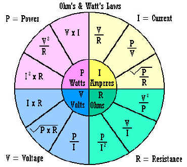
I = V ÷ R, V = I*R, R =
V ÷ I, and P (power in watts) = I*V are the fundamental formulas of Ohm's
law. (The * means to multiply the two quantities together). Where
V is the circuit voltage in volts, I is the circuits amperage in amps, and R
is the resistance in ohms.
Almost
every electrical and electronic circuit involves resistance, current and
voltage. This is why it is vital you understand the relationships
between them.
As an experiment you can set up a
circuit by connecting resistors in series with a battery, measure the
voltage across the resistors with a voltmeter, measure the current in the
circuit by placing an ammeter in series with the resistors and the battery.
If you know the voltages and current in the circuit you can use Ohms law to
calculate the resistance. With the resistor out of the circuit you can
measure it's resistance directly with an ohm meter. The multi-meters
today can measure ohms, volts and amperes (usually measured in milliamperes in
practical circuits) all in
one piece of test equipment.
Below
is a graphic chart showing the various relationships between resistance,
current, voltage, and power and shows how one unknown can be calculated if you know the
other two.

_._
6. CAPACITORS -
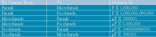
A capacitor is a device that stores an electrical charge when a potential difference (voltage) exists between two conductors which are usually two plates separated by a dielectric material (an insulating material like air, paper, or special chemicals between two sheets of aluminum foil). Capacitors block DC voltages and pass AC voltages. They are used as filters, AC coupling capacitors and as by-pass capacitors. They are also used in conjunction with resistors and inductors to form tuned circuits and timing circuits. A capacitors value C (in Farads) is dependent upon the ratio of the charge Q (in Coulombs) divided by the V (in volts). Common capacitors come in values of microfarads or Pico farads. Often you will have to convert between Pico farads and micro farads. A chart is provided below to assist in the conversion. For a list of capacitor terms defined: Click HERE. Measuring capacitance requires a capacitance meter. This is separate piece of test equipment. There are attachments for multimeters that allow measurement of capacitance directly. Also read this tutorial on how to test capacitors.
CAPACITOR Value Conversions:Some capacitors may be marked in micro farads and others of the same capacitance value marked in Pico farads. One Pico farad equals one micro-micro farad. You may need to make conversions between the two equivalents.
A capacitor marked 104M is a .001 uf +- 20%
1 micro F = 1000000 uuf 1 uuf = 1 pf .01 uf = 10000 pf .005 uf = 5000 pf .009 uf = 9000 pf .0001 uf = 100 pf .0005 uf = 500 pf .0009 uf = 900 pf
A capacitor marked 103M is a .01 uf +- 20%A capacitor marked 102M is a .1 uf +- 20%
Capacitance and capacitors - watch the video.
7. INDUCTORS -
 Inductors
are usually made with coils of wire. The wire coils are wound around
iron cores, ferrite cores, or other materials except in the case of an air
core inductor where there is no core other than air. The inductor
stores electrical charge in magnetic fields. When the magnetic field
collapses it induces an electrical charge back into the wire. Inductors
are associated with circuit capacitance and can form a tuned circuit and
resonate at a particular frequency. Two coils close to one
another, as they are in a transformer,
literally transfer charge from one coil to the other. This is called mutual
inductance.
Inductors
are usually made with coils of wire. The wire coils are wound around
iron cores, ferrite cores, or other materials except in the case of an air
core inductor where there is no core other than air. The inductor
stores electrical charge in magnetic fields. When the magnetic field
collapses it induces an electrical charge back into the wire. Inductors
are associated with circuit capacitance and can form a tuned circuit and
resonate at a particular frequency. Two coils close to one
another, as they are in a transformer,
literally transfer charge from one coil to the other. This is called mutual
inductance.
8. RESONANT
CIRCUITS - a
combination of capacitance, inductance and resistance.
Tuned circuits are found within electronic circuits where, for example, only one certain frequency is of interest. The filtering action of a tuned circuit is often associated with amplifiers as is found in a radios intermediate frequency stage. Only one frequency is amplified due to the filtering action of the tuned circuit. Tuned circuits may be designed for a very a narrow band of frequencies or with a wide bandwidth. Tuned circuits are also found in oscillators. Here the tuned circuit allows oscillations only at the tuned circuits resonant frequency in a properly designed circuit. Resonant circuits are a combination of inductance, capacitance and resistance. Please look at some of the links below for more detailed study of resonant circuits..
Tuned circuits are found within electronic circuits where, for example, only one certain frequency is of interest. The filtering action of a tuned circuit is often associated with amplifiers as is found in a radios intermediate frequency stage. Only one frequency is amplified due to the filtering action of the tuned circuit. Tuned circuits may be designed for a very a narrow band of frequencies or with a wide bandwidth. Tuned circuits are also found in oscillators. Here the tuned circuit allows oscillations only at the tuned circuits resonant frequency in a properly designed circuit. Resonant circuits are a combination of inductance, capacitance and resistance. Please look at some of the links below for more detailed study of resonant circuits..

_._


0 comments:
Post a Comment